Welcome to My Exploration of simulation of a typical Stirling engine
Stirling engines represent a unique and efficient approach to converting thermal energy into mechanical work, making them ideal candidates for sustainable energy solutions. Their ability to operate using various heat sources—be it solar, geothermal, or waste heat—positions them as a crucial technology in our quest for cleaner energy alternatives.
As global energy demands increase, traditional fossil fuel sources are becoming less viable, necessitating innovative technologies. Stirling engines offer remarkable advantages, including:
High Efficiency: With the potential to achieve greater efficiency than conventional combustion engines.
Environmental Friendliness: They produce minimal emissions, contributing to a cleaner planet.
Versatility: They can utilize a variety of heat sources, making them adaptable to different applications.
Problem Definition
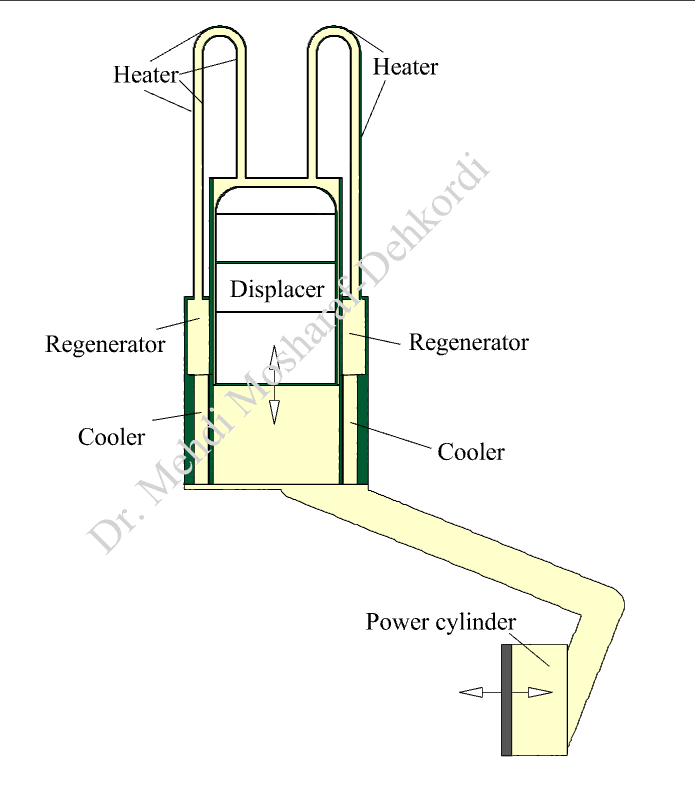
As schematically illustrated in the figure below, a Stirling engine comprises several essential components: two cylinders (the power cylinder and the displacer cylinder), pistons, two regenerators, two coolers, and heaters.
How the Stirling Engine Works:
Basic Principle: The Stirling engine operates on a closed-cycle regenerative heat process, utilizing an external heat source. It is driven by the cyclic expansion and contraction of a gas, usually air or helium, within the cylinders.
Operation Phases:
Heating Phase: The gas in the power cylinder is heated by an external source (the heater). As the gas heats up, it expands, pushing the power piston outward and generating mechanical work.
Cooling Phase: The displacer piston moves, transferring the hot gas to the cooler, where it loses heat. This results in the gas contracting and creating a low-pressure area.
Regeneration: The regenerators capture some of the heat from the gas before it cools down, which is then reused in the next cycle to improve efficiency.
Efficiency: Stirling engines are known for their high efficiency, often exceeding that of conventional internal combustion engines. This is partly due to their regenerative heat exchange, which minimizes energy loss.
The primary goal of our simulation is to study and enhance the design and performance of Stirling engines through detailed analysis that includes:
Coupled Fluid Flow and Heat Transfer Equations: This comprehensive approach allows for a better understanding of the intricate behaviors of fluids and thermal dynamics within the engine, leading to significant performance improvements.
Geometry along with boundary conditions
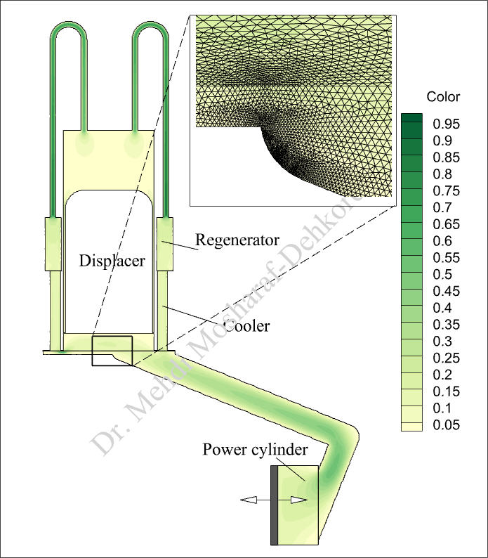
A portion of the computational grid
Assumptions, initial and boundary conditions
In the simulation of the Stirling engine, constant temperature boundary conditions are applied to the heater section and the cooler regions. Additionally, the positions of the displacer and power piston are defined by two functions that relate to the crankshaft angle.
Solution Approach and Computational aspects
In my exploration of Stirling engine design and performance, I have utilized advanced computational techniques, specifically the Finite Element Method (FEM). This approach is essential for gaining insights into the complex dynamics of these engines, particularly in the following areas:
Moving Mesh Strategies: By simulating the engine’s moving components, we can evaluate real-time performance and optimize geometries to enhance efficiency.
Non-Equilibrium Conditions in the Regenerator: By modeling the regenerator as porous media, we accurately simulate heat transfer processes, ensuring a realistic depiction of energy exchange.
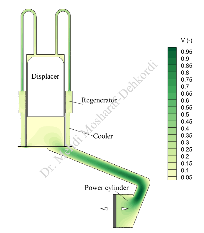
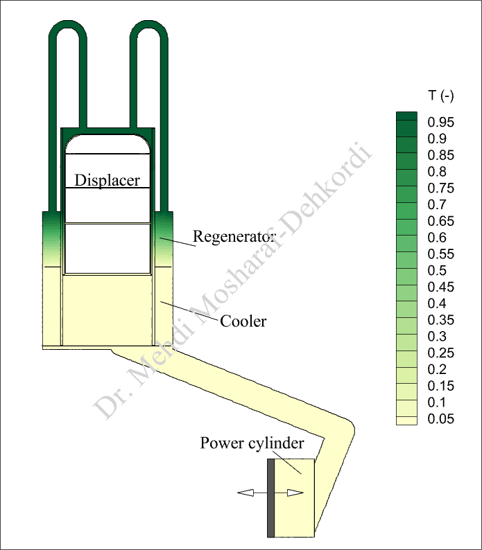
Numerical Results
1st cycle
1st cycle
The Evolution of the Stirling Engine: Watch the dance of its displacer and power pistons over time
Notes
To reduce the non-linearity of the equations, it is recommended to first solve the steady-state heat transfer within the engine. This involves keeping all moving parts stationary and the fluid at rest. The results from this steady-state solution will then serve as the initial conditions for the main transient analysis. This initial solution provides an acceptable approximation of the temperature-dependent properties, helping the main solver begin from a suitable starting point.
In this project, I simulated a Stirling engine by solving the governing equations related to fluid flow and heat transfer. Additionally, I implemented a moving mesh strategy to capture the interactions between the fluid and solid components of the system
Let’s work togetherto make innovations
For collaboration or inquiries, feel free to reach out! Contact me learn more about how my simulation skills can benefit your team and your project!